In machining, the cutting tool often looks like a small line item in total production cost. Yet a poorly chosen tool comes back as longer cycle times, unplanned machine stops, scrapped parts and inconsistent surface quality. That is why tool selection is an engineering decision rather than simply picking a product from a catalog.
In this article we cover the seven criteria that should be evaluated together when selecting a cutting tool, along with the most common mistakes we see on the shop floor.
1. Workpiece material and ISO material groups
Everything starts with the workpiece material. Tool manufacturers classify materials by machinability into six main groups defined in ISO 513, each marked with a color. Grade and geometry recommendations in catalogs are organized around these groups.
| Group | Color | Materials | Typical challenge |
|---|---|---|---|
| P | Blue | Steels | Chip control, crater wear |
| M | Yellow | Stainless steels | Adhesion, work hardening |
| K | Red | Cast irons | Abrasive structure, short chips |
| N | Green | Aluminum and non-ferrous metals | Built-up edge, chip evacuation |
| S | Orange | Superalloys and titanium | Heat concentration, work hardening |
| H | Grey | Hardened materials | High cutting forces, edge strength |
Even within one group, hardness, alloying elements and heat treatment make a real difference. A quenched and tempered steel such as 42CrMo4 is not machined with the same tool and parameters as a low-carbon structural steel.
2. Operation type: roughing or finishing?
In roughing, the goal is maximum metal removal per unit of time, so strong cutting edges, larger corner radii and tough grades come first. In finishing, dimensional accuracy and surface finish decide; sharp, positive geometries and wiper inserts are preferred.
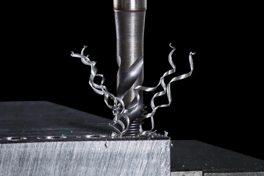
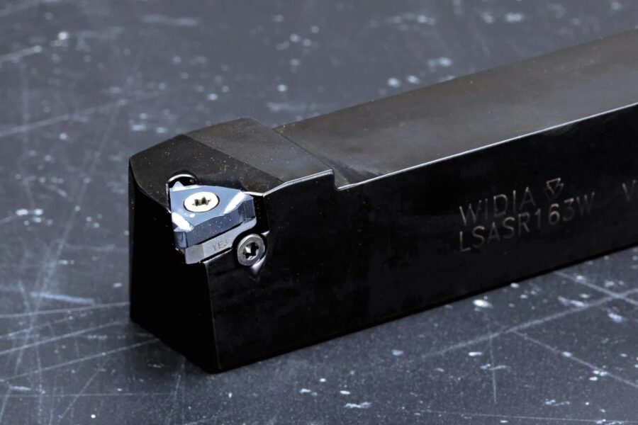
Milling, drilling, turning and threading each require their own tool family and selection logic. When one part involves several operations, balance reducing the number of tools against optimizing each operation.
3. Machine and fixturing rigidity
Even the best tool cannot perform in a system that lacks rigidity. Spindle power, torque, maximum speed and spindle interface should be considered together with how the part is clamped and how far the tool sticks out.
Using a simple beam model, tool deflection increases with the cube of overhang and decreases with the fourth power of tool diameter. Doubling the overhang increases deflection roughly eightfold. Therefore:
- Keep tool overhang as short as possible.
- Choose the largest tool diameter the geometry allows.
- In less rigid setups, prefer light-cutting, positive geometries.
4. Tool material and coating
Most machining today is done with cemented carbide tools. High-speed steel (HSS), cermet, ceramics, cubic boron nitride (CBN) and polycrystalline diamond (PCD) excel in specific applications:
- Carbide: The best balance of hardness and toughness for most materials.
- Cermet: High-speed finish turning of steels with excellent surface finish.
- Ceramics: High cutting speeds in superalloys and cast iron.
- CBN: Hardened steels and hard cast irons.
- PCD: Aluminum, composites and non-ferrous materials. Not suitable for steel because carbon diffuses into iron.
Coatings determine heat resistance, wear resistance and adhesion behavior. TiAlN/AlTiN and AlCrN coatings are common for high-temperature steel and superalloy machining. For aluminum, polished uncoated surfaces or DLC coatings are preferred to reduce adhesion.
5. Tool geometry
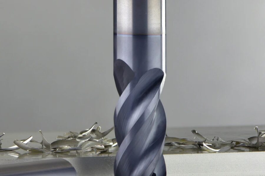
Number of flutes, helix angle, rake angle and corner form determine how a tool cuts. For long-chipping materials such as aluminum, end mills with fewer flutes (2–3) provide generous chip space; for steels, stiffer 4–6 flute designs are common. Variable helix or variable pitch tools break up the frequency of cutting forces and deliver calmer cutting in chatter-prone applications.
6. Cutting parameters
Tool selection cannot be separated from the parameters the tool will run at. The starting point is always the manufacturer’s recommended cutting speed (Vc) and feed per tooth (fz):
vf = fz × z × n
Here n is spindle speed (rpm), D is tool diameter (mm), z is the number of flutes and vf is table feed (mm/min). These values should be optimized step by step while monitoring tool wear and surface finish. We explain how parameters affect tool life in detail in our article on cutting parameters and tool life.
7. Cost per part
Tool price is only one part of the decision. The real metric is cost per part: tool cost, machine hourly rate, cycle time, tool change time and scrap rate must all be considered together.
A step-by-step tool selection process
- Define the part: Material and hardness, critical dimensions, tolerances and surface finish requirements.
- Sequence the operations: Roughing, semi-finishing and finishing, and how much stock each step removes.
- Identify the limits: Machine power, speed range, spindle interface, tool magazine and fixturing.
- Choose the tool family: Grade, coating and geometry suited to the material group.
- Calculate starting parameters: Adjust the manufacturer’s recommendation to your machine conditions.
- Test and measure: Record tool life, cycle time, dimensions and surface finish.
- Standardize: Add approved tools and parameters to work instructions and the CAM library.
The process may look long at first, but once done for a part family it greatly shortens selection time for future jobs and makes production repeatable.
Common mistakes
- Using the same tool and parameters across different material groups.
- Applying catalog values without considering machine and fixturing conditions.
- Running tools “until they break” instead of measuring tool life.
- Ignoring tool holder runout and cleanliness. We cover this in our tool holder selection article.