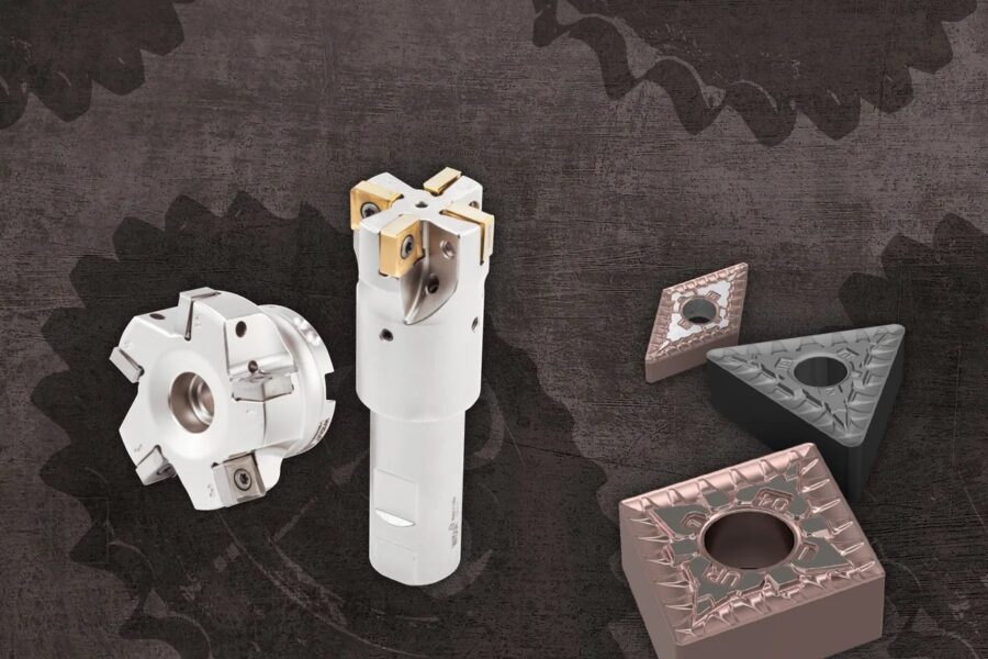
Turning productivity is largely determined by choosing the right insert and toolholder. Catalogs offer hundreds of options, but once you understand the ISO coding system and a few basic principles, selection becomes systematic.
How to read an ISO insert code
Indexable inserts are coded according to ISO 1832. Let us decode the common example CNMG 120408:
| Code | Meaning |
|---|---|
| C | Insert shape: 80° rhombic |
| N | Clearance angle: 0° (negative insert) |
| M | Tolerance class |
| G | Insert with hole and chipbreaker on both sides |
| 12 | Cutting edge length: approx. 12 mm |
| 04 | Insert thickness: 4.76 mm |
| 08 | Nose radius: 0.8 mm |
Letters added at the end (for example -PM, -MF) are usually manufacturer-specific chipbreaker and application designations, so check them in the manufacturer’s catalog.
Insert shape: balancing strength and access
As the corner angle increases, the cutting edge gets stronger and an insert offers more usable edges, but access to complex part profiles decreases.
- R (round): Highest edge strength; roughing and superalloys.
- S (90° square) and C (80°): Strong, general-purpose options for roughing and medium machining.
- W (80° trigon): Economical, multi-edge general-purpose insert.
- T (60°) and D (55°): Better access for profiling.
- V (35°): Best access, lowest edge strength; fine profile finishing.
Negative vs. positive inserts
Negative inserts (0° clearance) can be used on both sides, offer more edges and are robust in heavy cuts. Positive inserts generate lower cutting forces and suit thin-walled parts, small diameters, internal turning and less rigid setups.
Nose radius and surface finish
Theoretical profile height depends on feed per revolution and nose radius:
For example, with fn = 0.2 mm/rev and rε = 0.8 mm, theoretical Rt is about 6.25 µm. Doubling the feed quadruples this value. A larger nose radius gives a better finish and a stronger edge, but it increases radial forces and the risk of vibration.
Wiper inserts use a special corner form to achieve the same surface finish at higher feeds. Manufacturers typically state this increase as roughly double in many applications.
Chipbreaker and grade selection
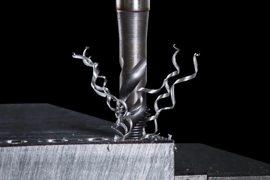
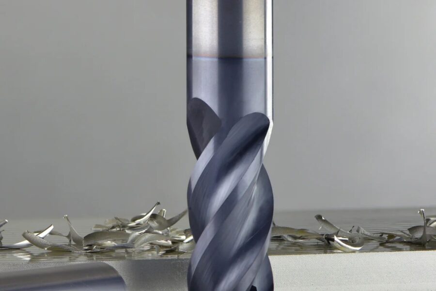
The chipbreaker makes sure chips break in a controlled way. Long, uncontrolled chips damage the surface, stop automation and put operator safety at risk. Finishing, medium and roughing chipbreakers should be used within the feed and depth ranges recommended by the manufacturer.
The general trend for coatings: thick CVD coatings provide high wear resistance for turning steel and cast iron, while thin PVD coatings suit stainless steel, superalloys and interrupted cuts that need a sharp edge.
Common turning problems and solutions
| Problem | Likely cause | Suggested fix |
|---|---|---|
| Vibration | Large nose radius, long overhang, weak clamping | Reduce the radius and overhang, try a positive insert |
| Long, uncontrolled chips | Running outside the chipbreaker range | Increase feed or depth, choose a different chipbreaker |
| Poor surface finish | High feed, built-up edge, worn edge | Reduce feed or use a wiper insert, increase Vc |
| Rapid flank wear | High cutting speed | Reduce Vc, choose a more wear-resistant grade |
| Edge chipping | Interrupted cut, excessive feed, brittle grade | Choose a tougher grade and stronger chipbreaker |
| Dimensional drift | Wear, thermal growth | Define a tool life criterion, measure more often |
Choosing inserts for unmanned and automated production
On robot-loaded machines and in lights-out production, predictability comes first. Rather than saving a few minutes of cycle time, choose inserts and grades that deliver reliable chip breaking, predictable tool life and stable dimensions. Sister tool definitions and tool life management should be standard practice on these lines.
Toolholder selection and ISO 5608 codes
Toolholder codes are standardized too. For example, PCLNR 2525M12: P (lever clamping), C (80° insert shape), L (95° entering angle), N (0° clearance), R (right hand), 2525 (25 × 25 mm shank), M (150 mm length), 12 (edge length). Choosing the largest possible shank and the shortest overhang is the most effective way to reduce vibration.
For parameter optimization, see our article on cutting parameters and tool life.