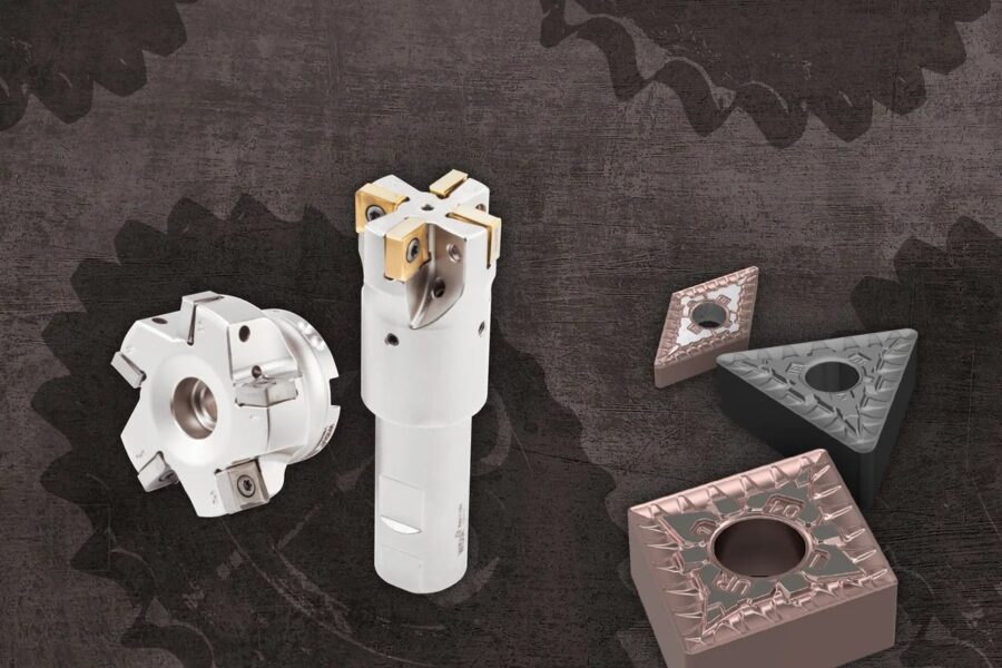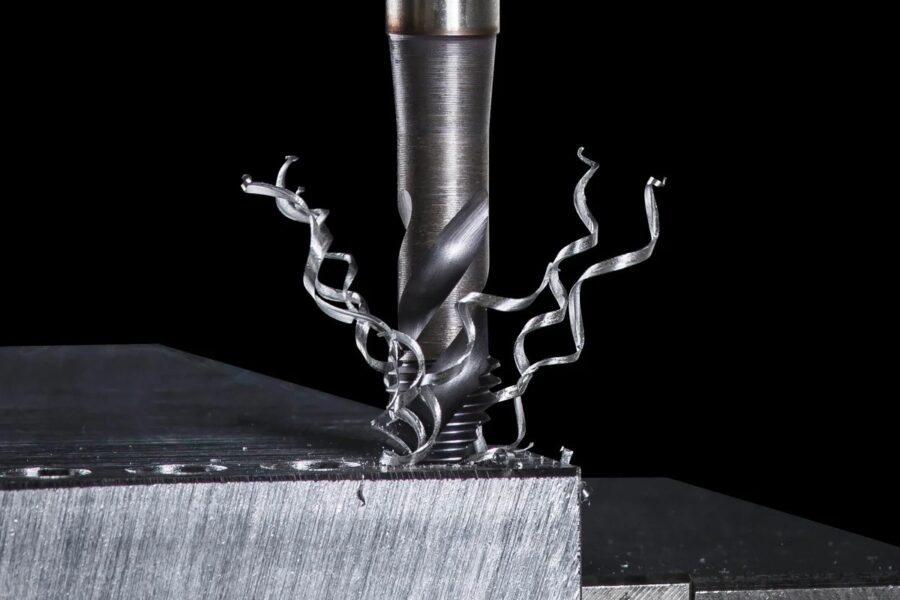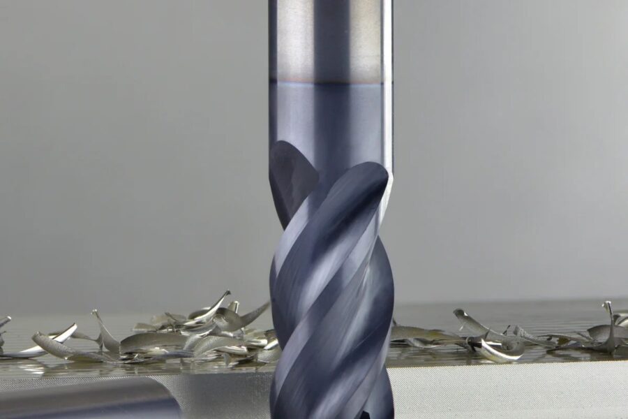
In mold and die making, parts are often machined after heat treatment, at high hardness. Hard milling, done with the right tool, strategy and machine, can reduce grinding and electrical discharge machining (EDM) steps and shorten lead times. In this article we summarize the key principles of successful milling in hardened steels.
What is hard milling?
Hard milling generally refers to milling hardened materials of roughly 45 HRC and above. In this range, cutting forces and the load on the cutting edge are high, and the rigidity of the tool, machine and fixturing becomes more important than ever.
Tool material and coating
- Fine-grain carbide: The core tool material for hard milling, used with heat-resistant AlTiN, AlCrN or TiSiN-based coatings.
- CBN: Delivers long life and stable dimensions at very high hardness, especially in finishing.
- Geometry: Negative or neutral rake, edge preparation (honing) and multi-flute designs are preferred for edge strength.
Cutting strategy
- Low radial engagement, high axial depth: Trochoidal and dynamic toolpaths limit the engagement angle and keep heat and force under control.
- Constant load: Sudden increases in engagement in corners are the most common cause of tool breakage. Load-controlled toolpaths in CAM software reduce this risk.
- Climb milling: Chips form from thick to thin, reducing impact and heat at the edge.
- Rest machining: Cleaning excess material in corners with small tools before finishing leaves an even stock allowance for the finishing tool.
Effective diameter of ball nose cutters
The diameter that actually cuts on a ball nose end mill depends on the depth of cut. In shallow cuts it is much smaller than the nominal diameter:
If spindle speed is calculated from the nominal diameter, the actual cutting speed stays too low. At the center of the tool axis, cutting speed is zero; on 5-axis machines, tilting the tool about 10–15° relative to the surface improves both surface finish and tool life.
Surface finish and scallop height
In ball nose finishing passes, the peak height left between two adjacent passes (scallop height) is approximated as:
For example, with a Ø6 mm ball nose cutter (R = 3 mm) and a 0.2 mm stepover, theoretical scallop height is about 1.7 µm. Halving the stepover reduces scallop height to a quarter but doubles machining time. The right balance should also account for the polishing work that follows.
Constant-Z (z-level) toolpaths give more consistent surfaces on steep walls, while raster or spiral toolpaths work better on shallow areas.
A step-by-step finishing strategy
- Roughing: Remove most of the volume with trochoidal toolpaths, leaving an even stock allowance.
- Semi-finishing: Bring the stock allowance to the same level on every surface. A constant load on the finishing tool is the key to dimensional consistency.
- Rest machining: Clean remaining material in corners with smaller tools.
- Finishing: Use constant-Z on steep surfaces and raster or spiral paths on shallow ones; calculate the stepover from the target scallop height.
- Inspection: Measure tool wear and dimensions, and update parameters for the next parts.
Machine and control requirements
In hard milling, a thermally stable spindle, a fast look-ahead control and correctly set contour tolerances make a big difference. High-precision modes on the CNC prevent feed fluctuations on finishing paths made of small segments, improving both surface finish and tool life. Completing a machine warm-up cycle before long finishing operations reduces dimensional drift.
Coolant and rigidity
In hard milling, flood coolant can cause thermal cracks as the edge heats and cools in interrupted cuts. That is why air blast or minimum quantity lubrication is preferred in most applications. Keep tool overhang as short as possible and use a holder with high runout accuracy; shrink fit holders are common here. See our tool holder selection article for details.